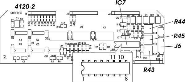
Disconnect the cable that goes to the head support from J6 on the kV selector board (4120-2).
On the kV selector board (4120-2) short pins 10 and 11 on IC 7.
Make sure that the X-ray unit is NOT in the READY position.
Adjust trimmer R43 on 4120-2 to set the kV value to 63 kV. Note that when adjusting the trimmer the TA switch on the PLU board must be in the DOWN position (the kV light will NOT change). To check that you have got the correct kV turn the TA switch to the up position (the kV light will then change).
Remove the short from pins 10 and 11 and reconnect the head support cable to J6.
Close the temple supports as far as they will go.
Adjust trimmer R45 to set the kV value to 67 kV. Remember to toggle the TA switch during adjustment and verification until you get the correct value.
Open the temple supports as far as they will go.
Adjust trimmer R44 to set the kV value to 79 kV. Remember to toggle the TA switch during adjustment and verification until you get the correct value.
The head support calibration is now complete.
NOTE The kV range from 67 – 79 is based on: Kodak T-MAT G / Lanex Regular film/screen combination (400 speed) at 6 mA with spinal compensation ON